As the purpose of the CNC machine is to cut and carve foam, I did some testing, adapted some hot wire tools for the purpose and cut some foam I had lying around.
Cutting the logo of Aliptera
Using a hot wire tool:
Tried some 3D carving. The melted foam didn't have where to go so the bad result is expected.
It is time to talk about the tools used to build the machine.
A drill press, bought specially for this purpose from Kijiji.
A miter saw I borrowed from my friend Ion, Ion thank you for lending it to me, without it I would have a hard time cutting all those aluminum profiles!
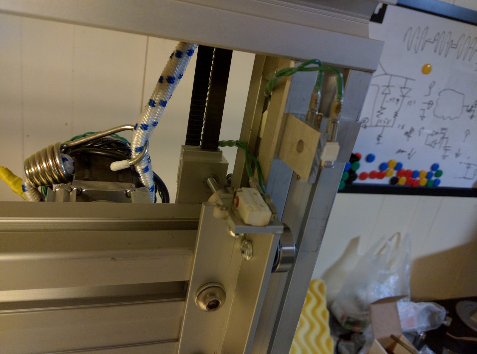
This is the most complicated thing of the whole enchilada.
In order to move the whole beam up and down, it has two driving belts, one for each end of the beam, driven together by a shaft.
To counter balance the weight of the beam and Y mechanical axis, I choose to use constant force springs, instead of weights for the purpose of reducing the inertia.
The constant force springs are expensive, so for now I'm using a low-tech approach, bungee-cords.
Something is wrong with the computer running the LinuxCNC. As I generate steps in software I need it to be fast. I'm getting errors in the real time kernel. Eventually I figured it out: The thermal paste on the heat-sink have dried out and provided inadequate cooling to the CPU.
Motors:
Choice was between stepper motors and DC servo motors; I decided stepper motors would be easier to control. I ordered 3 stepper motors from AliExpress: link
I decided to use belts for converting rotational movement of the steppers to translational movement. They are faster, low noise, and cheaper than lead-screw used generally for this purpose. I found a nice site selling belts, gears and all kind of useful stuff: http://www.robotdigg.com/
The machine would have a fixed frame, as it offers more rigidity, having a table moving in X axis, a gantry moving on the Z axis and a tool holder moving on the gantry along the Y axis.
A rotating axis "A" axis could be added to rotate the tool or on the table, rotating the work-piece.
The frame:
After some research I decided to build the machine out of "baltic birch" plywood. The sliding prismatic joint should be made by bearings on aluminium profiles. It should look something like this:
I found some discarded aluminium framing materials, I decided to make the frame out of that, as it confers more rigidity and more important it is not subjected to warping as the wood is and also I can use it as a basis for the prismatic joints as well.
While building prototypes of concept model lip wing aircraft, presented on aliptera.com website, I run into cutting by hand complex curved shapes for the wings and fuselage.
The work was tedious at least, the model didn't look very good and it took forever to make.
I reached the conclusion I need a CNC machine to do the complex shapes I want.
It needs to be able to cut foam in 3D, making complex shapes. For this I think a loop of nichrome wire of 1/4 -1/2 inch diameter would do nicely. To ensure rigidity of the loop some thicker gauge wire should be used.
I would like to use it also for cutting/engraving aluminum, wood, plexiglass.
Size: As big as possible. 4 x 3 x 3 ft would be nice.