Posts

Building another fixed wing trainer aircraft

Image
 I'm building a smaller trainer aircraft to be able to fly in the local park.

Modifying the transition lip-wing single copter

Image
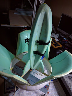
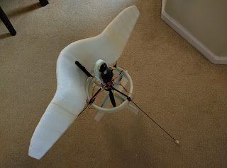
 We reached the conclusion that we don't have enough control authority with three control surfaces in the propeller slipstream. We're modifying the prototype and adding a fourth one. May the fourth be with us!

Building the transition lip-wing single copter

Image
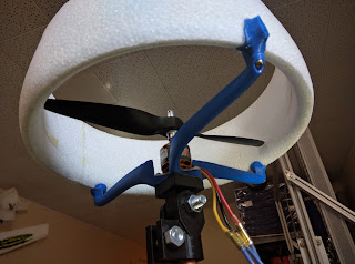
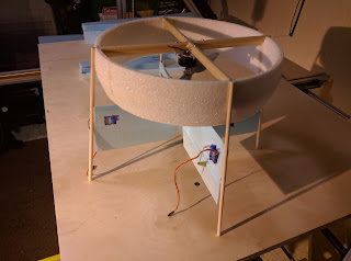
 Most efficient flying is wing-borne flying, taking advantage of the awesome L/D ratio that wings are providing. I'm building a single copter having a lip wing to try and achieve transition.

Finishing and testing the tri-lip-wing single copter

Image
 Since it has three lip wings I'm calling this concept tri-lip-wing single copter. The testing is during my vacation at Myrtle Beach, since it was too cold in Canada.

Cutting parts for the lip-wing single copter

Image
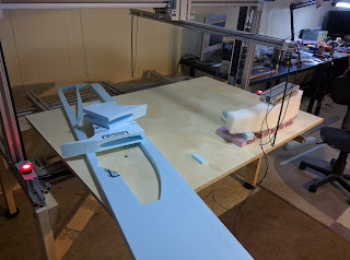
 The most efficient rotorcraft is a single rotor, so this is what I'm building. I'm cutting the parts on my new CNC machine. The parts are from Home Depot blue extruded polystyrene foam. I'm also adding a layer of fibreglass for rigidity.

Cutting parts and building a trainer fixed wing aircraft on my CNC machine

Image
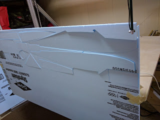
 I'm building a trainer aircraft to stay current in my flying skills - or actually I should say learning how to fly. So, I'm cutting parts for a trainer fixed wing aircraft. The inspiration I got it from the 'Blue Baby', see more details about the original build here https://www.rcgroups.com/forums/showthread.php?681556-%2A%2A-Blu-Baby-Primary-Trainer-%2A%2A-Plans-Pics-and-Fun%21

Cable carrier and E-stop switches installation

Image
I finally managed to install the cable carriers and the E-stop switches. The machine looks better and better now.

More wiring

Image
I've received the cable carrier drag chain and emergency stop buttons on Friday. I need to install them on the machine

Cutting some foam

Image
As the purpose of the CNC machine is to cut and carve foam, I did some testing, adapted some hot wire tools for the purpose and cut some foam I had lying around. Cutting the logo of Aliptera Using a hot wire tool: Tried some 3D carving. The melted foam didn't have where to go so the bad result is expected. The tool used: Some more "Art"

Tools used to build the machine

Image
It is time to talk about the tools used to build the machine. A drill press, bought specially for this purpose from Kijiji. A miter saw I borrowed from my friend Ion, Ion thank you for lending it to me, without it I would have a hard time cutting all those aluminum profiles! A bench grinder I made; A hand drill and various other hand tools.

Wiring and table fittment

Image
Last weekend I didn't do too much: I cut the table out of birch plywood, it is not yet attached to the moving X axis frame; I mounted the electronics and did some wiring. I found some neat locations for the home position switches and wired them:

Building a base for the machine

Image
I decided to build a wooden base for the machine.

First 3D real test

Image
The 3D "pen" test

Building the X axis

Image
As I'm gaining experience building this thing, It seems to go faster and easier,  maybe I'm seeing the finish?

Testing the Z and Y axes

Image
They are working fine!

Z axis mechanical drive

Image
This is the most complicated thing of the whole enchilada. In order to move the whole beam up and down, it has two driving belts, one for each end of the beam, driven together by a shaft. To counter balance the weight of the beam and Y mechanical axis, I choose to use constant force springs, instead of weights for the purpose of reducing the inertia. The constant force springs are expensive, so for now I'm using a low-tech approach, bungee-cords.
Received printed idler gear

Image
I have received the 3D printed idler gear today. Thank you Alex for printing them for me! They look really nice. Thank you Cristian for helping me modifying the source file so the model accepts 608Z ball bearings I already have. Working on the belt tensioner: